Very satisfied! I was searching for several days, but nope; till I discovered your webside and there it was at a very reasonable price. Keep up the good work!
Paul
Flanders
I purchased the unit from a private party and the original owners manual was not available. Having the ability to download it was extremely helpful and clarified operating the equipment immensely. This is a complicated unit and without the manual I would not have been able to maximize it's potential. Thank you.
Being a user of older radios of many kinds, preferring them over more modern rigs, this manual was invaluable in the programming of my two. I now know for certain what the assorted buttons functions are, and am very grateful to have found this excellent site. Many thanks for your assistance, Tony.
Text excerpt from page 9 (click to view)
Installation (cont.)
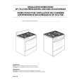
Installing 4-Wire Power Cord
Wires from range
(Number of wires on each terminal can vary)
! WARNING
To avoid the risk of severe electrical shock or death, ground wire must be attached to frame of range, using ground screw provided. Ground wire must not contact any other terminal. 1. Remove rear wire cover on back of range. 2. Place strain relief (winged clamp) in cord access hole below terminal block. � Strain relief is supplied with cord. Place wings through hole entering from bottom. � Screw holes in clamp should be below mounting panel. 3. Remove green ground screw (retain for use in step 8) and unscrew brass nut on center terminal. Remove grounding strap.
A
B
A
Wires from power cord
A� Power lead terminal (Connect black or red insulated wire and secure with brass nut.) B� Neutral terminal (Connect insulated white insulated wire and secure with brass nut.) Installing 4-Wire Power Cord
Wires from range
(Number of wires on each terminal can vary)
Center terminal nut
8. Position grounding strap down and away from terminal block. Attach green or bare wire and grounding strap to back of range using green ground screw previously removed in step 3.
Grounding strap Green ground screw
Terminal Block Grounding Strap, Screw and Center Nut
Wires from range
(Number of wires on each terminal can vary)
4. Place cord through strain relief. 5. Attach cord neutral (center) or white wire to center terminal on terminal block. Secure with hex nuts provided. 6. Attach power lead, red wire or black wire to left terminal. Secure with hex nuts provided. 7. Attach power lead, red wire or black wire to right terminal. Secure with hex nuts provided.
A
Wires from power cord
A� Ground screw (Connect green insulated wire and secure with screw.) Position Grounding Strap
9. Firmly tighten all connections to ensure proper electrical connection. 10. Place screw through strain relief, tighten, and replace rear wire cover.